
Views: 0 Author: Site Editor Publish Time: 2026-09-16 Origin: Site


Facility managers often notice a frustrating gap between manufacturer-advertised compaction ratios and actual loading dock performance. You might expect a massive reduction in waste volume based on a glossy brochure. However, the reality inside the chamber often tells a completely different story. Miscalculating the expected compaction ratio leads to serious operational headaches. Over-specifying equipment wastes valuable capital expenditure upfront. Under-specifying results in excessive hauling fees, bloated trash footprints, and severe operational bottlenecks during peak hours.
To project true performance accurately, you must evaluate both material science and mechanical engineering. Understanding waste composition, hydraulic force, chamber design, and automated thresholds is non-negotiable. You cannot rely on theoretical numbers alone. You need verifiable metrics based on your specific waste stream. This guide breaks down the core factors that dictate your equipment's actual efficiency. We will explore how to align mechanical specifications with your operational realities to achieve maximum payload density.
Waste Profile Dictates Performance: A 4:1 or 5:1 ratio is highly dependent on the elimination of air pockets; wet, dense, or rigid materials yield significantly lower actual compaction rates unless liquids are actively managed.
Hydraulic Force vs. Structural Integrity: High compression requires not just high PSI, but a reinforced container capable of withstanding sustained outward pressure without warping.
Sizing Matters for Throughput: Selecting between an 8 CBM or 10 CBM unit changes the baseline volume calculation, influences the required ram penetration depth, and dictates the overall reduction of your facility's trash footprint.
The Overweight Risk: Maximizing the mobile waste compactor compression ratio can inadvertently lead to exceeding legal road weight limits for hauling, requiring a careful balance of density and payload capacity.
The standard mathematical formula for compaction is straightforward. You divide the starting volume of loose trash by the ending volume of compacted trash. If you put four cubic yards of loose cardboard into a chamber and compress it down to one cubic yard, you achieve a 4:1 ratio. However, a massive difference exists between theoretical volume reduction and operational payload density. Marketing claims often highlight theoretical maximums achieved under perfect laboratory conditions. Operational payload density measures the actual weight of the material you can legally and safely pack into the container before hauling.
Many buyers see extreme claims of 7:1 or 7.5:1 and expect those results on their loading docks. These numbers are highly misleading for mobile units. Such extreme ratios typically apply to specialized vertical balers or stationary industrial units processing uniform, highly compressible materials. Standard mobile units usually achieve ratios between 2:1 and 4:1. A specialized high compression mobile waste compactor can push closer to 5:1 under optimal conditions. Understanding this baseline prevents unrealistic expectations and flawed equipment sizing.
When evaluating the mobile waste compactor compression ratio, you must look at the loose yardage generated by your facility versus the compacted yardage inside the receiver box. A hospital generating massive amounts of loose plastic packaging will see a drastically different ratio than a grocery store disposing of heavy, wet produce. The ratio is not a static feature of the machine; it is a dynamic result of the machine interacting with your specific refuse.
The hydraulic ram is the workhorse of any mobile trash compactor. The mechanical process relies on brute force delivered through a steel platen. The ram pushes deep into the chamber, applying immense pressure to the waste. This action crushes air pockets, flattens bulky items, and forces irregular shapes to interlock. The effectiveness of this process depends entirely on the hydraulic system's ability to maintain force against increasing resistance as the container fills.
Modern units utilize automated thresholds to optimize cycle times. Programmable logic controllers (PLCs) and photo-eyes monitor the hopper. Once waste reaches a designated threshold, the system triggers a compression cycle automatically. This automation ensures consistent material density. It removes the reliance on manual operator intervention, preventing the chamber from overflowing or under-compressing. The system runs the ram forward until it hits a predetermined pressure spike, indicating the load is packed tight.
Furthermore, sustained pressure is vital. The ram must hold the waste under pressure for a specific duration at the end of the stroke, known as dwell time. This sustained force prevents material memory expansion, ensuring the trash stays compacted once the ram retracts. Without adequate dwell time, resilient materials simply bounce back, instantly degrading your hard-earned density.
Your specific waste stream dictates the final payload density more than any mechanical specification. Municipal Solid Waste (MSW) provides a reliable baseline. Mixed general waste typically yields a 3:1 to 4:1 ratio. It contains a mix of compressible packaging and denser food waste. The moisture content in MSW fluctuates by season, which slightly alters the final weight, but the volume reduction remains relatively stable.
Corrugated cardboard and empty plastic containers yield the highest visual compression ratios. These materials consist mostly of trapped air. When the ram crushes them, the volume reduction is dramatic, often approaching 5:1. However, cardboard tends to bridge in the hopper. It forms a structural arch that prevents material from falling into the charge chamber. Overcoming this requires a ram with an aggressive breaker bar at the pinch point to shear the cardboard and force it downward.
Wet waste and dense organics present a completely different challenge. You cannot compress liquids. When a chamber fills with wet organic matter, the ram encounters the hydraulic lock effect. The fluid has nowhere to go, halting the ram's forward progress regardless of the system's PSI. To combat this, you must integrate liquid drainage systems. Removing fluid volume drastically improves the compression ratio of the remaining solid mass. Sloped floors and drain ports allow the liquid to escape into a sanitary sewer line, freeing up valuable cubic yardage inside the container.
Rigid industrial waste requires different tactics. Wood pallets, metal scraps, or thick rigid plastics resist standard compression. These materials often require pre-crushing mechanisms or specialized shear blades mounted on the ram to break them down before packing. If you attempt to crush heavy wooden pallets with a standard ram, you risk snapping the guide shoes or bowing the platen face.
Material springback, often called memory, actively fights your compaction efforts. Materials like rubber, foam, and certain resilient plastics naturally want to return to their original shape after pressure is removed. If you compress a load of foam packaging, it will immediately expand the moment the ram retracts, ruining your density metrics and pushing waste back into the charge chamber.
Equipment design must counteract this phenomenon. Retention teeth, or retention dogs, are essential components welded inside the chamber walls. As the ram pushes waste past these teeth, they grab the material and prevent it from sliding backward during the ram's return stroke. Combined with sustained ram pressure at full extension, retention teeth effectively neutralize springback. This mechanical synergy maintains the achieved density and maximizes the available space for the next load.
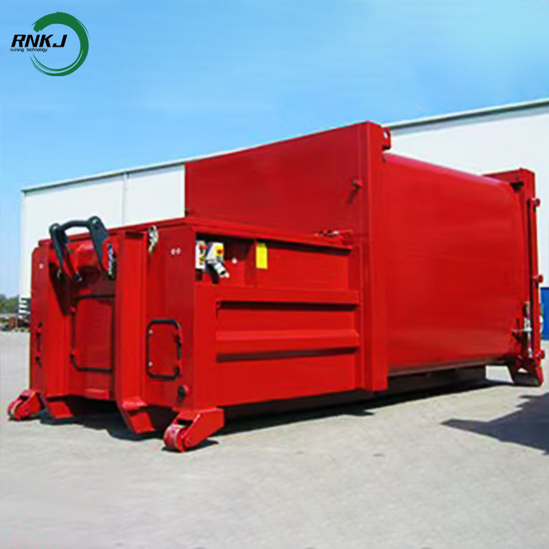
The heart of the machine lies in its hydraulic specifications. System pressure, measured in PSI, and cylinder bore size directly correlate to the crushing force applied to the waste. A larger cylinder bore operating at high PSI generates massive forward thrust. Force is calculated by multiplying the system pressure by the surface area of the cylinder piston. Therefore, a 6-inch cylinder operating at 2000 PSI delivers significantly more packing force than a 4-inch cylinder operating at the same pressure.
The hydraulic power unit (HPU) drives this entire process. The motor horsepower and the pump's gallons per minute (GPM) rating determine the speed of the ram. A high GPM pump moves the ram quickly, reducing cycle times. However, raw force and speed are only part of the equation. Ram penetration depth is equally critical to the overall success of the operation.
The ram must penetrate deeply into the container to prevent bridging at the entrance. Deep penetration ensures uniform density throughout the entire load. It forces the material to pack tightly against the rear doors and sidewalls. Without adequate penetration, you will haul containers that are heavy at the front but virtually empty at the back. A long stroke length guarantees the ram pushes the waste far enough into the receiver box to clear the charge chamber completely.
Choosing the correct container volume requires balancing your physical footprint against your daily waste generation. An 8 CBM high compression mobile compactor serves as the optimal solution for facilities facing strict spatial constraints. Urban retail centers, hospitals with tight loading docks, or sites with restricted turning radii benefit immensely from this smaller footprint. It maximizes density in a compact area, effectively reducing the overall trash footprint without requiring extensive site modifications or concrete pad extensions.
Conversely, high-throughput environments demand larger baseline capacities. A 10 CBM high compression mobile compactor fits perfectly in large manufacturing plants, distribution centers, or sprawling retail complexes. The larger capacity drastically reduces hauling frequency. You pack more tons per pull, which directly lowers transportation costs. It minimizes operational downtime caused by waiting for haulers to swap full containers. The choice between the two depends entirely on your site's physical layout, truck access, and your daily tonnage.
Purchasing waste management equipment requires a strict evaluation framework. You must calculate the return based on reduced hauling frequency and optimized space utilization against the upfront capital cost. High-compression machinery costs more initially, but the reduction in monthly hauling fees often yields a rapid payback period. You must map specific machine features to your desired operational outcomes to ensure you specify the correct build.
Sometimes, off-the-shelf units fall short. You must know when to specify a custom high compression waste compactor. If your waste stream contains high liquid content, you need integrated drainage sumps and fully sealed tailgate doors. If you use automated tippers to empty bins, you need specialized hopper designs with flared lips. If you process abrasive industrial waste, you must demand reinforced steel plating on the ram face and chamber floor to prevent premature wear and tear.
| Waste Material Type | Expected Compression Ratio | Primary Compaction Challenge | Required Equipment Feature |
|---|---|---|---|
| Corrugated Cardboard (OCC) | 4:1 to 5:1 | High volume, fast accumulation, bridging | Deep ram penetration, aggressive breaker bar |
| Mixed Municipal Solid Waste | 3:1 to 4:1 | Variable density, moderate moisture | Standard retention teeth, automated PLCs |
| Wet Organics / Food Waste | 1.5:1 to 2:1 | Hydraulic lock, liquid displacement | Integrated liquid drainage sumps, sealed doors |
| Rigid Plastics / Wood Pallets | 2:1 to 3:1 | Material springback, structural resistance | Shear blades, heavy-duty cylinder bore |
| Textiles and Foam Packaging | 3:1 to 4:1 | Extreme material memory and expansion | Extended dwell time, heavy-duty retention dogs |
Engineering always involves trade-offs. Higher compression ratios require heavier gauge steel. The container must withstand immense outward pressure without deforming, bowing, or blowing out the side panels. This reinforced steel significantly increases the tare weight of the mobile unit. A heavier empty machine means you have less allowable payload weight before hitting road limits. You are trading mobility and payload capacity for structural integrity.
Another major trade-off exists between speed and force. Fast cycle times are necessary for high-traffic loading docks where employees constantly dump trash. A high GPM pump achieves this speed. However, fast cycles often sacrifice the slower, sustained pressure required for maximum material density. You must decide whether your operation prioritizes rapid processing to prevent dock bottlenecks or maximum density to reduce hauling costs. Two-stage pumps offer a compromise, providing a fast approach speed followed by a high-pressure, low-speed packing phase.
Achieving a massive compaction ratio introduces a hidden operational failure. You might pack the waste so densely that the container exceeds Department of Transportation (DOT) or local road weight limits before it is physically full. Haulers will refuse to pull overweight containers, or they will hit you with severe overweight fines. A standard roll-off truck has strict axle weight limits. If you pack ten tons of wet waste into a small container, the truck might be illegal for the road, even if the container is only half full by volume.
You must implement mitigation strategies to prevent this scenario. Integrating pressure gauges on the hydraulic system helps estimate load weight based on the resistance the ram encounters. Fullness monitors provide visual or digital alerts when the system hits specific pressure spikes. The most accurate solution involves installing load cells under the compactor frame. These cells weigh the unit in real-time, alerting operators to stop loading exactly when the payload reaches the maximum legal limit, regardless of the remaining physical volume inside the box.
Selecting a reliable OEM dictates the long-term success of your installation. You must evaluate a waste compactor manufacturer based on strict criteria. Do not accept theoretical ratio claims printed on a spec sheet. Demand verifiable case studies from facilities processing similar waste streams. Look closely at the fabrication quality. Are the structural welds continuous, or are they stitch-welded? Continuous welds provide superior strength and prevent liquid leakage.
Look closely at their support infrastructure. A robust local service network is mandatory. Hydraulic hoses blow, cylinders leak, and PLCs require troubleshooting. You cannot afford days of downtime waiting for parts to ship across the country. Scrutinize the warranty coverage on hydraulic components and demand structural guarantees on the container itself. A reputable manufacturer will stand behind their steel fabrication, their pressure ratings, and their electrical components.
Audit your facility's waste stream to identify the primary materials, moisture content, and presence of rigid items that resist crushing.
Calculate your maximum allowable hauling weight based on local road regulations and your specific hauler's truck axle capacity.
Select the appropriate CBM size that fits your physical dock space while minimizing your monthly hauling frequency.
Specify the exact hydraulic cylinder bore, pump GPM, and automation requirements needed to handle your specific trash profile.
Request a pilot test or trial period from your shortlisted vendor to validate performance metrics on your actual loading dock.
A: A realistic operational ratio falls between 2:1 and 5:1, depending heavily on the waste type and machine specifications. Claims of 7:1 or higher usually apply to stationary balers processing uniform cardboard, not mobile units handling mixed waste streams.
A: Air-filled materials like cardboard and plastic bottles compress highly, yielding great ratios. Liquids and dense organics cannot be compressed due to hydraulic lock, requiring drainage or specialized handling to achieve any meaningful volume reduction.
A: An 8 CBM unit is ideal for facilities with tight footprint constraints and lower daily waste generation. A 10 CBM unit is designed for higher volume throughput, significantly reducing hauling frequency for large retail or manufacturing sites.
A: Yes. Packing waste too densely can cause the container to exceed legal DOT road weight limits before it is physically full. You must monitor payload weight using load cells or hydraulic pressure sensors to avoid heavy fines.
A: You need a custom unit when dealing with non-standard waste streams. Scenarios include high liquid content requiring integrated drainage sumps, extreme weather environments requiring heated power units, or unique loading dock configurations needing specialized hoppers.
A: Never rely solely on brochures. Ask for reference sites currently processing similar waste streams. Request detailed structural steel specifications and insist on utilizing a trial period to test the machine on your actual loading dock.


